Types of Electric motors used in EVs.

BY AFZAL YOUSAF
Electric motors are the main motive source of EVs. Working together with batteries, motor converts electrical energy into rotational energy and then into mechanical movement in wheels. Electric motor is usually referred as the "Heart" of the electric vehicle and it should have certain features to make it suitable for e mobility. As an ev enthusiasts and professional, when we look at the specifications of EVs, we find different types of motors are used like BLDC. PMSM, ACIM etc.
In this article you can find the different types of motors used in EV.
Types of motors used in EVs are following:-
- Direct current motor (DC)
- Brushless Direct current motor (BLDC)
- Alternate current Induction motor (ACIM)
- Permanent magnet synchronous motor (PMSM)
- Swithched reluctance motor (SRM)
DC MOTOR
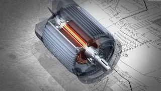
DC Motor is an electric motor working on Direct current and converts it into mechanical energy. Main parts of the DC Motor are Stator, Rotor, Yoke, Poles, Stator Winding, Armature Winding, Commutator and Brushes. It works on the principle of Lorentz Law where Current carrying conductor is placed in a magnetic field, it experience a force.
Dc motors are widely used for tractions as they posses high starting torque, ability to withstand sudden increase in load, easy to control, simple construction and Low cost. Apart from this, drawbacks are they need electrical contacts and due to carbon brushes , they need regular maintenance. Because of this drawbacks, DC Motors practically becomes out of EV market.
BLDC MOTOR
Brushless DC Motor are similar to DC motor but it do not have the brushes. It have features like High starting torque, High power efficiency, High power density, excellent stability, Easy to control, Simple construction, Low cost and Low maintenance.
In BLDC Motor, the windings are not on the rotor but on the stator., while it is the rotor that have the permanent magnets. As Windings are static, combination of brushes and rotory switch is not necessary. BLDC motor speed can be controlled by varying input Voltage or current.
Because of all these features and wide availability, BLDC motors are preferred in E-bikes, E rickshaws, medium power electric vehicles.
Click here to read the details of construction and working of BLDC Motor.
AC INDUCTION MOTOR
AC Induction motor (works on alternating current) or asynchronous motor is an AC electric motor in which the electric current in the rotor needed to produce torque,which is obtained by electromagnetic induction from the magnetic field of the stator winding. Rotor of induction motor are of two types:-
- Squirrel cage
- Wound type
They are widely used in Electric cars and Buses because of high efficiency, good speed regulation, less maintenance due to absence of commutators and brushes. Its weight is much more that makes it impractical to use in small electric vehicles.
PMSM
This type of motor is synchronous type with a permanent magnet and is used as a rotor to create poles and works in Alternate Current. Main difference between PMSM and Induction motor is in the rotor. Rotor is placed inside the stator and its efficiency is slightly higher than induction motor. Maintenance is less as it is brushless and is classified in to two types based on magnets attached to rotor.
- Surface PMSM
- Interior PMSM
PMSM is highly stable, compact size and produce high initial torque due to permanent magnet. Also have high power-to-size ratio. Now PMSM is widely used in electric vehicles especially cars, light commercial vehicles and buses.
SRM
Switched reluctance motor also called variable reluctance motor works on the principle of Variable reluctance. In variable reluctance principle rotor always tries to align along the lowest reluctance path and a switching inverter is there to control the motor. On the basis of construction, they are classified into two.
- Singly salient construction
- Doubly salient construction


Thank you. keep reading and supporting.
ReplyDeleteمقالة ممتازة
ReplyDeleteThank you. Keep Reading.
DeleteThank you. Keep Supporting.
ReplyDeleteAadab
ReplyDeleteI want to convert Omni Van.
Engine Replaced with Bldc. Fuel-tank + more places LiPhO4 Btry.
Probable weight including 8Men and Bags..After Conversion = 1600Kg
BLDC flange fitted to Clutch box flange.
Gear Ratio Remains
1st Gear 1:
Maruti Omni Van
Kerb Wt =800Kg + 8 men + bags 800Kg = 1600Kg
Wheels diameter = 53.7 cm – Tyre Yield 1.7 = 52cm = 0.52m
Radius = 0.26m
However Circumference remains same 168.7 or 1.68 m/rotation after slippage.
𝑎 = 𝑣 ÷ 𝑡 ; F = m x 𝑎 ; Torque = F x r of wheel
𝑎=60,480m/hr÷16.8s= 16.8m/s÷ 16.8s = 1m/s2
F=1600kg x 1m/s2= 1600N
Torque required to move van will be in excess of = 1600N x 0.26m radius= 416Nm say 420Nm
1st gr
Differential ratio is approximately 3:1,
TG ratio is approximately 3.5:1.
Therefore total ratio in the first gear is:
𝑡𝑜𝑡𝑎𝑙 𝑟𝑎𝑡𝑖𝑜 = 3 ∗ 3.5 = 10.5
(For example, one EMRAX 228 motor can deliver 240 Nm peak torque Pt and 120 Nm continuous torque. Therefore peak torque on the wheels in first gear is:
𝑡𝑜𝑡𝑎𝑙 𝑝𝑒𝑎𝑘 𝑡𝑜𝑟𝑞𝑢𝑒 𝑜𝑛 𝑡ℎ𝑒 𝑤ℎ𝑒𝑒𝑙𝑠 𝑖𝑛 𝑓𝑖𝑟𝑠𝑡 𝑔𝑒𝑎𝑟 = 12 ∗ 240 𝑁𝑚 = 2880 𝑁𝑚
10.5 x Pt= 420Nm
Pt=420/10.5=40Nm
In this case close to 3000 Nm of peak torque in first gear can be expected.
Torque, power calculation:
𝑷 [𝒌𝑾] = 𝒏 [𝑹𝑷𝑴] ∗ 𝑴𝒕 [𝑵𝒎] / 𝟗𝟓𝟓𝟎
Mt=torque [Nm] Motor Torque
P=power [kW]
Power Consumed
n=motor rotation [RPM] =
1 Rotation = 1.68 mtr for r=0.26m 10Rotation/s = 16.8m/s For wheel
10*3=30Rotations/s at 4th gr or 1800RPM=n
Pkw= n*40Nm/9550= n/238.75= 1800/238.75=7.54 kw
+ 0.06 kw to overcome mech-Losses
8 Kw
At lower RPM (motor rotation), you can expect lower motor power consumption at the same torque.
At higher motor speed you can expect higher motor power consumption at the same torque.
3rd gr speed expected is 20-50 kmph GrRatio is 1:1.2
2nd gr speed expected is 10-30 kmph GrRatio is 1:1.9
1st gr speed expected is 00-10 kmph GrRatio is 1:3.5
So the torque is same but power used is lesser.